About our Company
Service to Offset Printing

Hi-Tech Blanket Conversion
Printers Blankets Conversion Technology means somewhat beyond cutting rubberised fabrics with knife and ruler.
Please check how Professional Format Conversion can assist in equalising blanket response all over format area and increase printing life.
I – The Format Edge Frontier
- Frontier stands for discontinuity. Unique situations invariably occur at frontiers, requiring further attention and often diverse analysis tools.
At different materials’ interface, shear stresses are the inevitable candidates to further analysis.
At abrupt frontiers – solid/liquid, or solid/gas – issues will often switch from shear to geometric, chemical resistance, meteorological, contamination,…Blankets are layered composites, where metal terminals are the only conventional raw material.
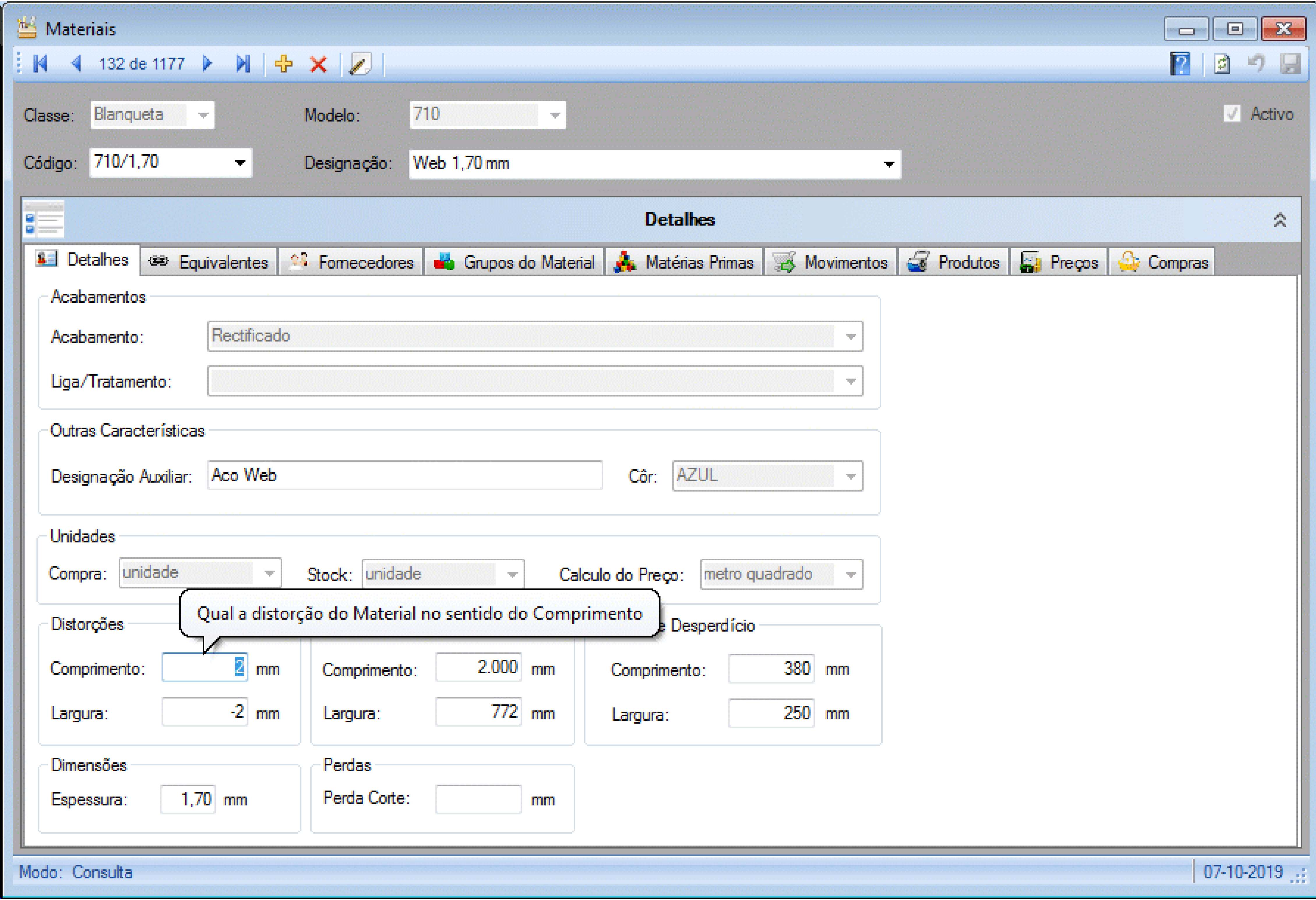
- The traditional format cutting method, using a dragging blade, implies a non-negligible local deformation of blanket material.
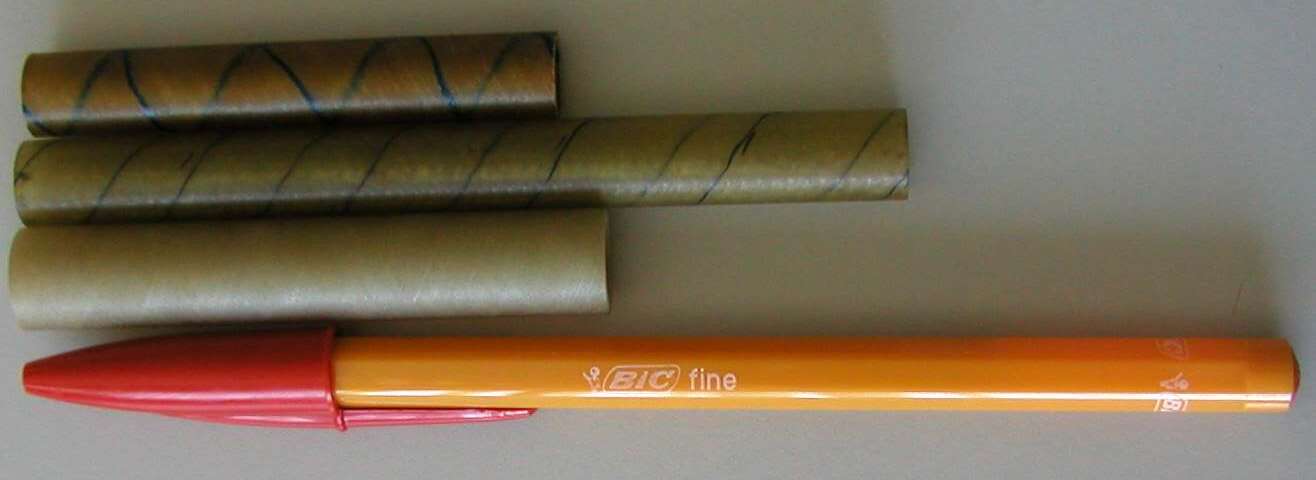
Even before effective cutting starts, rubber will distort as soon as the blade tip initiates its travel. - A further characteristic feature of blanket material is that a straight line cut will produce two distorted edges.
This is a direct consequence of carcass fabrics pre-stressing and varies with cloth and blanket manufacturing recipes.
Distortion level varies according to the cutting direction, along or across the warp threads. It is most easily detected close to format corners.
Another feature is that measured distortion is mostly independent of format size.
Distortion does affect blanket printing performance and should not be ignored, or considered as an unsurmountable doom.
Cutting alternatives
Printers Blankets Conversion Technology did not suddenly appear ready out from the blue. It was the result of much thought and testing work, during a comprehensive research and development process:
- Several cutting method and cutting equipment alternatives were considered, aimed to achieve the lowest possible blanket reaction and distortion.
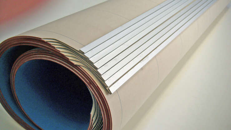
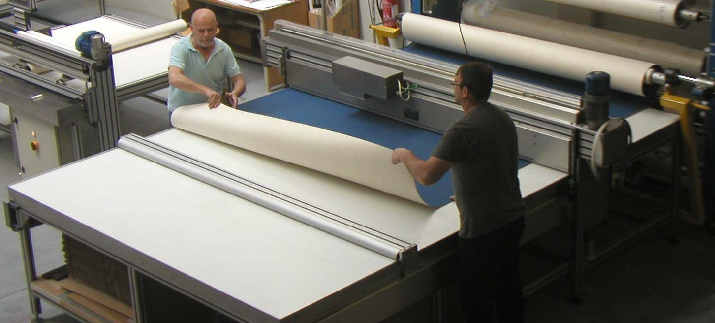
- Format pre-cut followed by all-around narrow strip trimming was the preferred cutting method, to optimise format squareness and dimensional tolerances.
With two-stage format cutting the pre-cut operation can be carried with blanket surface rubber facing upwards, for easier defect inspection.
Afterwards, all-round trimming may be safely carried with surface rubber facing down, thus producing less and shorter free cotton fibrils. - As to the equipment, it was decided to assist the cutting operation with ultrasound technology.
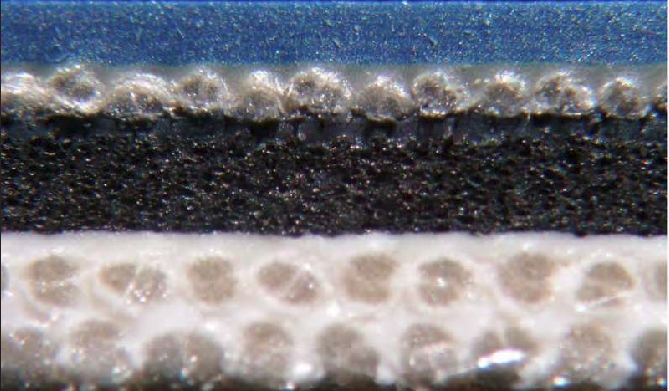
- Format edge structure (cross-section) can also benefit from optimised conversion procedures, thus contributing to extended blanket printing life.
Ultrasound Technology
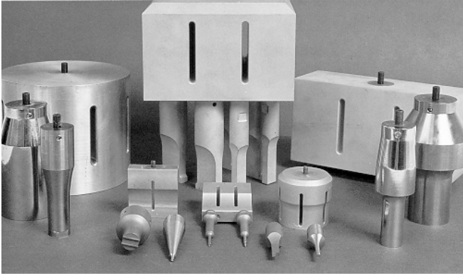
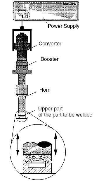
Converter (left) Booster (centre) and Horn (right) train
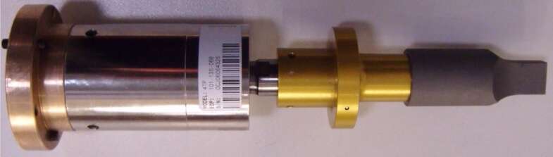
Existing Flanges at Vibration Free Nodes offer Fixing Point alternatives
II – Ultrasound Technology
- A practical application of an ultrasound equipment consists of:
- A 50-60 Hz frequency mains alternating current feeds an ultrasound oscillator.
It produces an electrical high tension oscillatory signal, usually of up to a few kV and at a frequency ranging between 20 and 40kHz.
- A converter transforms the electrical oscillatory energy into mechanical vibration – the ultrasound.
The converter is constituted by a lead zirconate titanate ceramic disk stack with strong piezoelectric characteristics.
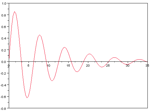
Like helical springs (and unlike a string) it produces an axial vibration, which amplitude may typically reach ~ 25 µm. - The horn delivers the vibration generated by the converter to the load. Quite often a mechanical booster conveniently pre-shapes horn vibration.
- When a duly tuned booster (or horn) receives ultrasound vibration, its dimensions will no longer be constant.
Minute length variations will occur at the applied frequency, causing a corresponding sequence of tensile or compression intern structural stresses.
Even a minor structural flaw will develop into a crack, sooner or later, and the component will stop functioning.
Thus both horns and boosters use often titanium as raw material. - Unlike boosters and besides imparting often a significant magnifying factor on vibration amplitude, horn shape reflects its interface environment peculiarities.
Horn proportions require highly skilled machining and ultrasound design know-how as they need to deliver very sharp resonant peaks.
Ultrasound applications and peculiarities
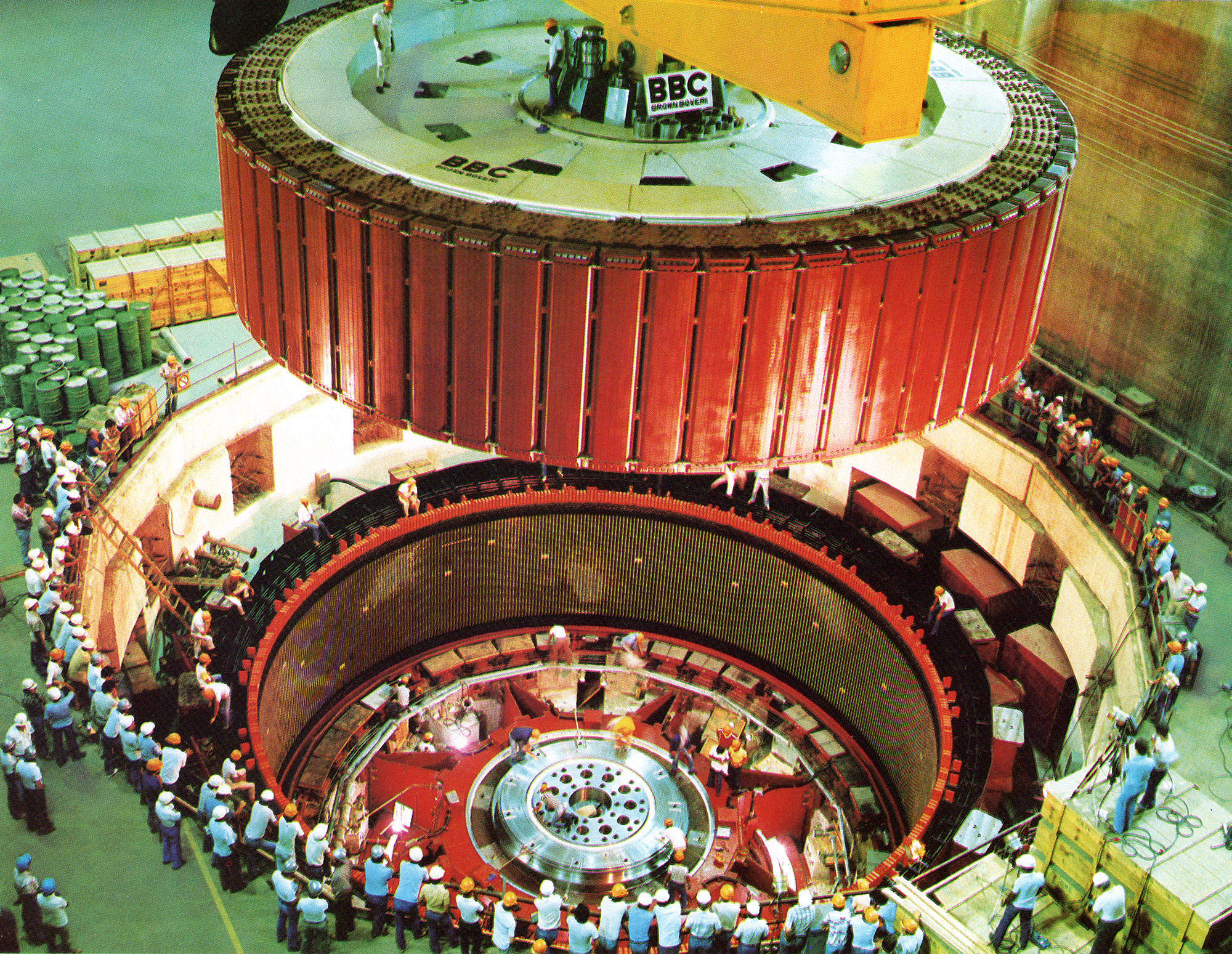
- Motor components industry makes extensive use of Ultrasound technology. An example is to weld into one piece different coloured plastic elements, to form appealing headlamp covers.
- Another current ultrasound application is on highly demanding metal surface cleaning, like aircraft and precision watch components. Ultrasound frequencies are sharply above fluid response range capabilities and solids immersed in cleansing liquids can be subject to cavitation.
- Similarly, Printers Blankets Conversion Technology does also take advantage of Ultrasound convenient features:
- The following video clip illustrates how horn vibration creates substantial wind activity at its frontier proximity.
It promptly induces water waves while bubbling starts after a short time lapse.
- Despite its minute amplitude, horn oscillatory activity causes two distinct reactions beyond the solid boundary of this multiple element Frontier.
- As the horn vibrates, it can be unmistakeably felt that, close to the tip, its lateral surfaces become “lubricated” with intense low pressure wind activity.
- The air film separating the horn tip from the water surface is far too thin to avoid the disturbance caused by metal vibration from being intensely felt on water surface.
- In present experiment horn tip must not touch the water surface. The ultrasound energy transferred directly to the water would exceed generator’s output, causing it to stop working.
III – Preserving Oscillator Quality Factor
- Let us consider a horn vibrating at ultrasonic frequency with its edge applied with suitable pressure to the load system.
It originates a sequence of impacts at the horn/load-system interface with a substantial amount of heat energy generated. - The performance of highly efficient Ultrasound systems will be affected by any dimensional modification of their mechanical components.
In conclusion, heat generated at the horn tip/load interface should be prevented to increase horn temperature.
Once again, after extensive consideration, an exclusive “spot cooling” method was added to Printers Blankets Conversion Technology:
- Temperature buildup at the “hot” source will be mainly left unchanged, while avoiding heat transmission to the horn’s bulk.
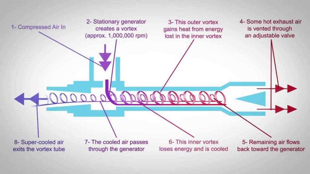
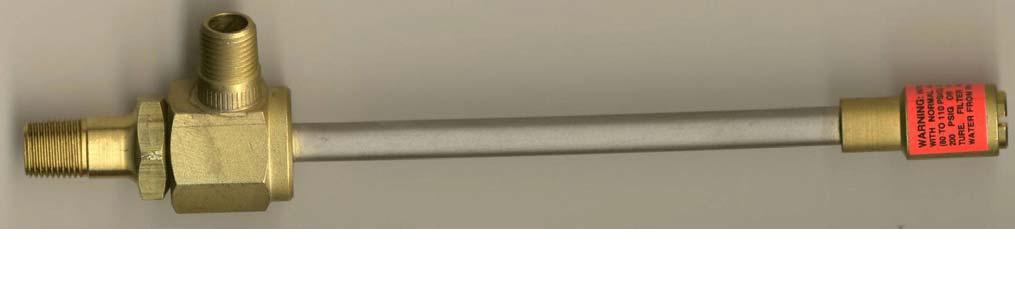
- A Vortex cooling device fed by compressed air provides a glacial cold air stream headed at the horn tip.
Thus, adequate cooling grants optimum efficiency during the ultrasound operation.
- Cooling effect can be chosen from Vortex devices range, according to the heat power delivered by the ultrasound equipment.
- Setting the adjustable valve at hot tube end will prevent eventual ice buildup at the super cold Vortex output.
- Careful choice of high quality horn tip material is essential to enable safe operation under extremely sharp temperature gradient conditions.
Vortex Technology
Stationary cooling engine
IV – Printers Blankets Conversion Technology – High Frequency Impact Cutting
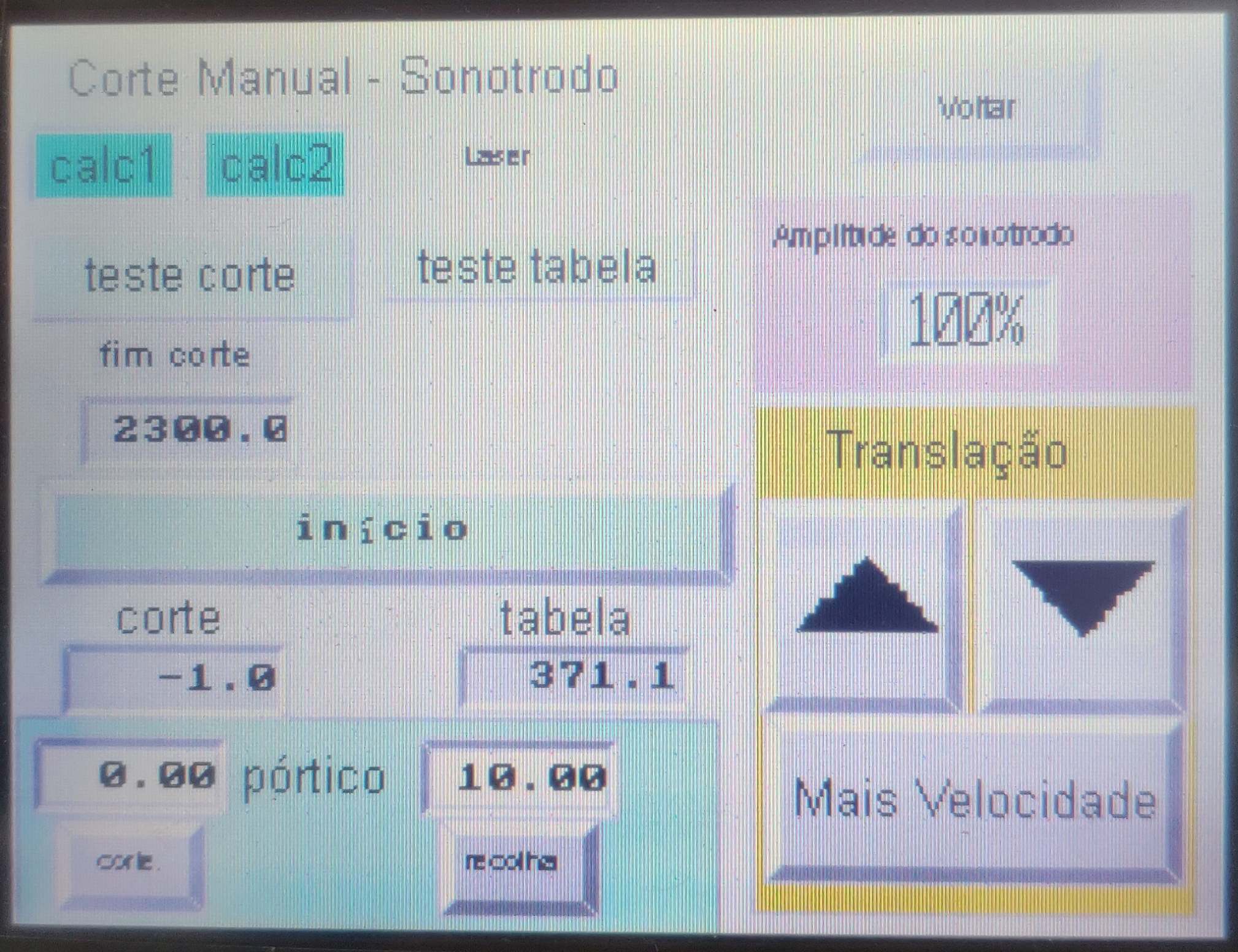
- A 30 kHz ultrasound generator was installed on a 4-axis digital processor controlled cutting table.
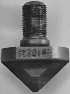
- The linked pop up picture shows a titanium horn fitted with a hard metal blade bit.
- Firstly, the ultrasound-assisted cutting head uses the normal dragging blade principle during its translation movement.
Further to the translation movement, the cutting blade delivers over 60 impacts per each millimetre of cut blanket.Rubber reaction to such high rate of sharp impacts becomes mostly similar to that of a rigid solid.
Our cutting operation achieves a comfortable cruise speed around 500 mm/s. - Translation speed exceeds over 50 % that of a normal dragging blade. Furthermore, a “happy”, higher pitched, cutting noise confirms a much lower rubber composite reaction.
- A Vortex stationary engine directs a cold-air-stream at blade tip, preventing heat propagation to the horn material. The Ultrasound vibration friction energy concentrates at the blade-tip/blanket-material interface.
- During the cutting operation, the cutting interface achieves an extremely high temperature, but still not sufficient to affect Hard-Metal-Tip performance.
- But as cutting operation proceeds, this high temperature consistently shrinks and cauterises cotton threads’ delicate loose fibrils.
V – The Fabric/Glue Interface
- Traditional barring with liquid resin grants a good bar pullout strength provided bars are not subject to shock.
- Further features of traditional gluing method are:
It requires a relatively long cure cycle. Barred blanket formats must wait several hours, or even days, before they can be safely mounted on the press.
It does not provide dependable flat bar gluing. In fact, rigid resin joints do not stand peeling stresses as it may occur during blanket mounting. The bending operation of blanket gripper edges into the gap channel becomes somewhat awkward.
In search of excellence
- A number of alternatives were studied before deciding to replace liquid glue by thermoplastic tape. It was also decided to assist blanket barring with ultrasound technology.
Once again Printers Blankets Conversion Technology uses both Ultrasound heating and Vortex cooling techniques.
- A Vortex glacial air stream directed at the horn/carcass fabric interface keeps duly checked both horn and blanket heat buildup.
- A thermoplastic tape anchors precisely to the format in an ultrasound assisted operation.
Thus the tape is conveniently kept in place during the subsequent bar fitting and pressing operations.
A heated press provides finally the desired bar-to-fabric bonding effect. - On its linear travel, the ultrasound fed horn delivers the thermoplastic tape onto the format gripper edges.
- The rectangular shaped horn has its tip grooved to reduce the amount of energy transferred to the blanket. The resulting localised pressure increase does also improve gluing adhesion efficiency.
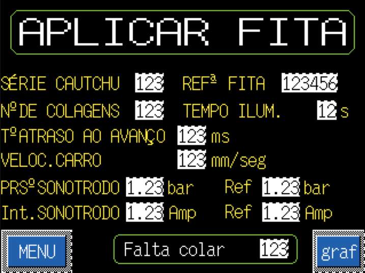
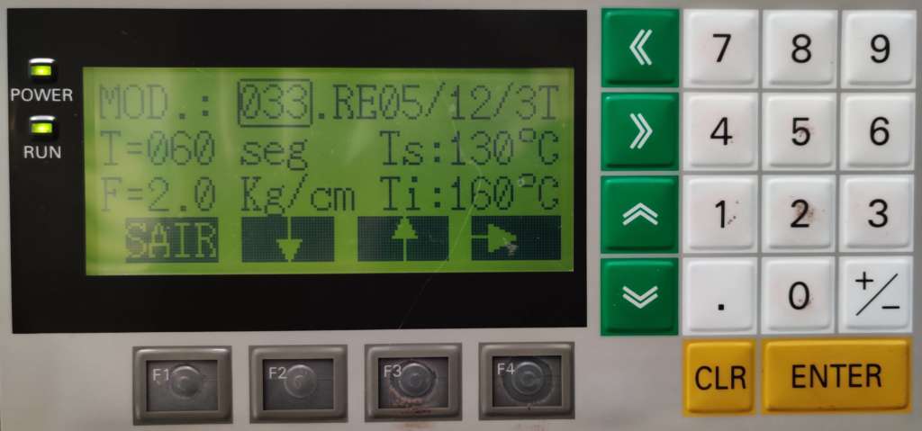
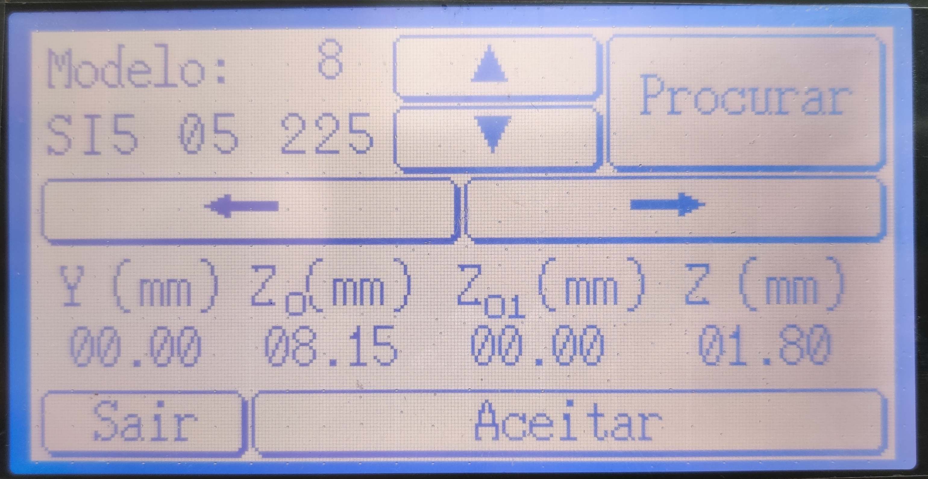
- The operation parameters are programmable:
– Initial pressure applied by the horn on the carcass fabric and pressure range limits.
– Delay time before starting movement, after the horn is lowered onto the format.
– Horn translation speed.
– Electric current fed to the ultrasound generator and current range limits. - To each blanket model corresponds a specific set of parameter values, including the applicable glue tape grade.
A processor controlling the semi-automatic tape application operation selects the applicable gluing details.
VI – Fabric Reaction to Vibration
- Gluing takes place as ultrasound vibration reaches the free surface of the first-fabric-ply through the melted tape.
- Let us consider the “extended” Oscillatory System. It comprises Generator to Load where ultrasound frequency vibratory energy means shock and friction.
- The Load converts the mechanical energy into heat, reducing the unloaded Oscillatory System’s Quality Factor, Q. It just flattens oscillatory amplitude, keeping other characteristics very much unchanged.
- However, local stress conditions of each warp thread determines additional reactions to the applied vibration. Every fill thread has a confinement effect on local warp stress condition, not constant along warp threads’ length.
- This Load reaction engages additional energy, that does not generate heat. It has, instead, the capacity to alter applied Ultrasound energy effectiveness. It is the segment of Fabric Ply Reactive Reaction to the applied ultrasound frequency vibration.
Ultrasound energy ultimately delivered to the “tape/carcass fabric” load varies with the Phase Angle between applied oscillation and reactive reaction. Local warp thread tension condition does interfere with the intended gluing effect on the fabric. - When a resonant reaction develops during glue tape application, former operation stability – with a predominately active reaction – is lost.
Most likely, effective Ultrasound energy will become either scarce to achieve sufficient gluing adhesion, or develop instead too high temperatures. The adjustment of Gluing Parameters can preserve original operation efficiency, thus counteracting warp response modification.
Beyond Glue Tape application
- Further to enable more precise format geometry, Printers Blankets Conversion Technology became also source of better blanket printing reaction understanding.
- Control Panel resources of our tape application table afford prompt adjustment of above parameters back into adequate gluing performance. But the operators have immediate evidence that the particular blanket batch should be brought under closer CQ Scrutiny.
- It becomes thus strikingly apparent whenever a blanket batch has a different response from its “standard” behaviour.
- Fairly occasionally, (poorly manufactured or designed) blanket models exist where most batches will require significant parameter adjustments.
VII – Printers Blankets Conversion Technology & Printing Performance
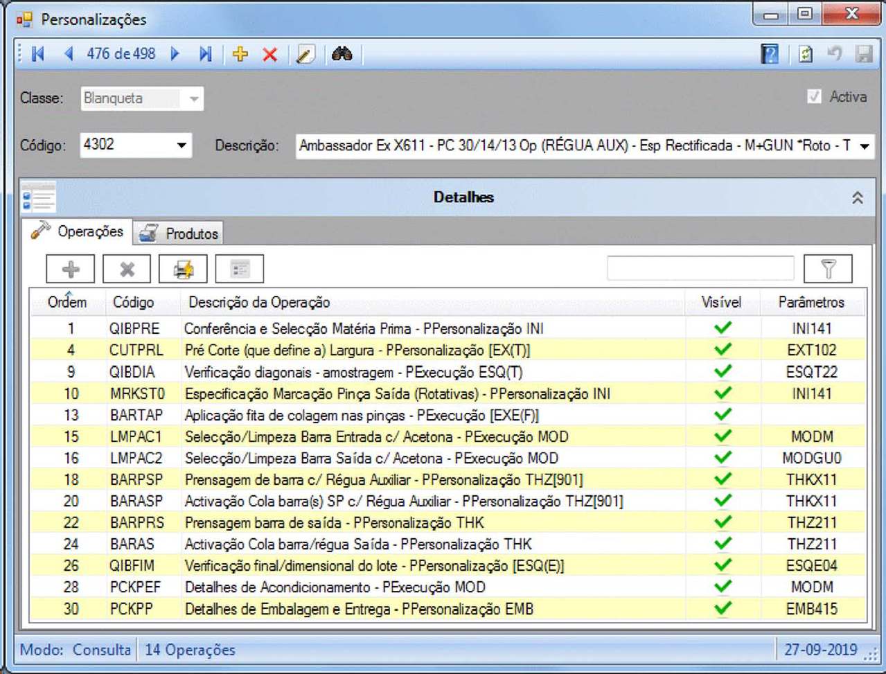
- Following list describes current IberoWIN Conversion Manual procedures and also printers blankets conversion technology developments carried at Iberográfica. They have substantive influence in printing performance and advisory capacity.
- Ultrasound assisted cutting contributes to lower the distortion of format edges. It also effectively grants lower liquid intake by the carcass.
- Choice and judicious use of format edge sealant varnish does also contribute to shield blanket structure integrity..
- Two-stage cutting technique with final trimming-out of narrow clippings reduces gripper edge warping and improves dimensional tolerances. It also substantially improves squareness rigueur of barred formats.
Blanket material is duly kept under confinement in the close vicinity of the cutting line during the cutting operation. This unique provision further reduces inevitable blanket distortion. - Ultrasound assisted gluing provides a precise means to use solid glue tape for barring purposes.
- The use of Vortex cooling enables a precise tape gluing operation, preserving blanket structure integrity.
The same cooling effect maximises ultrasound cutting efficiency, with “laser-like” surface finish. Format cutting with laser beam was rejected due to inevitable generation of noxious gases associated to laser operation. - Careful bar design without sharp corners or edges ensures maximum grip and dependable blanket use.
- The activation press uses moderate temperature during a generous heating cycle time. While pressed bar thickness is improved, rubber and tape plasticiser degradation are avoided.
Printers Blankets Conversion Technology – Quality Control
- Printers Blankets Conversion Technology includes a sequence of Quality Control procedures, focused on dimensional optimisation, to warrant consistent delivery of professional formats.
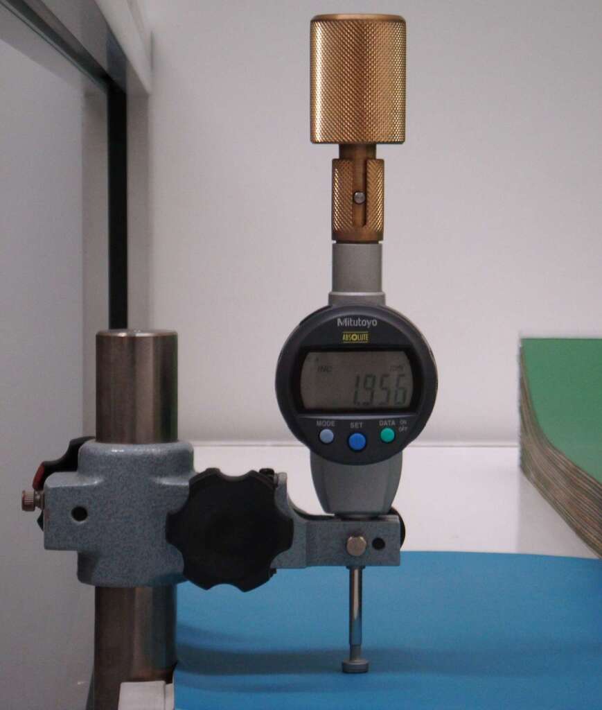
- At production, in-line use of precision deadweight thickness measurement equipment enables prompt response to the most stringent printers’ needs.
- Each delivery grants adequate format protection and package, including moisture protection wrapping film, to meet specific transport, storage and use conditions.
VIII – Conclusions
- As it invariably happens with engineering problem analysis, printers blankets conversion technology research was the source of substantive performance improvement.
- When a blanket requires systematic parameter adjustments to accept glue tape, probably it will also require recurrent pre-press attention.
- Blanket reactions both to the tape gluing with ultrasound and during the printing operation may have resonant components. The importance of these disturbing reactions varies with blanket design and manufacturing tolerances.